AERODYNAMICS.
AERODYNAMICS.
© TONY FOALE 1986 - 1997
Articles on aerodynamics usually concern themselves with extolling the virtues of low drag and the accompanying effects on performance and fuel economy. But the creation of slippery motorcycles is probably the easy bit. In common with all medium to high speed vehicles the effects of wind pressure on stability must be considered, but not unexpectedly this becomes very complex on a bike compared to self balancing machines such as cars. Our old friend, gyroscopic precessional force and its interaction with the steering, is the cause of many stability problems not present on cars, lorries, etc.. Let's look at some of these problems and see if
DRAG.
Firstly, let's consider just what causes air drag ------ which is after all the largest thief of our engine power output at all but the lowest of speeds. Drag is a force trying to prevent rapid movement of a bike though the air, this force is generated though a difference in pressure between the front and rear of the machine. This pressure difference acts on the frontal area of the bike to give the drag force, hence the larger the frontal area the greater is the drag. As the bike moves though the air it must force aside the gas molecules, if this is done gently at lowish speed these molecules will follow closely the outside shape of the machine and little resistance will be generated. This is only possible with a well streamlined shape, such as the classic teardrop. Under these conditions the flow is said to be laminar and most of the drag comes from the frictional forces as the air particles actually rub against each other along side the body. In practice, the flow is usually turbulent, not laminar, and the drag is much higher. As the name suggests, this flow regime (turbulent) is confused and comprises many swirling eddies near the surface. These eddies are caused by the inability of the air to follow the sudden changes of shape that abound on a bike or car body. The momentum of the air particles tends to keep them on a straightish path but when the shape of the body departs too much from the ideal, then the air no longer follows the shape and friction between adjacent layers of air, moving at different velocities, tends to 'trip' the air flow into eddies. The object moving through the air then leaves a turbulent wake behind and studies have shown that the drag force is approximately proportional to the size of this wake. The size and shape of the object and the speed are the most significant factors affecting the size of this wake. In order to numerically compare the aerodynamic qualities of different shapes a dimensionless parameter known as Cd. is used. It is sometimes incorrectly stated that a flat plate being pushed though the air has a Cd. of 1.0. This refers only to a special theoretical case when all the air ahead of the plate is pushed away in front of it, and none is spilt around the sides. In reality the Cd. of a flat plate depends on its size and may be closer to 0.5. The whole question of size is a very interesting one, because it affects the validity of extrapolating the results from model tests to the real machine. Wind tunnels large enough to accept a full sized bike or car are very expensive to build and run, and so if model tests can be meaningful a great deal of money can be saved, always a favourite with the manufacturers. However, the use of models is not always plain sailing. There are the fairly obvious problems such as accuracy, e.g. a tolerance of 1 mm. on the real thing becomes a tolerance of 0.2 mm. on a fifth scale model. A less obvious but equally important consideration is that of Reynolds No.. Mr. Reynolds, an early investigator into fluid flow, discovered, that the air speed at which the turbulence characteristics of similar shaped but different sized objects was dependent on their size. In fact, if you half the size of your object you need to double the air speed, this effect was formalised into a mathematical expression known as the Reynolds No.. In order to achieve similar flow patterns over different size models we need to try and keep this number constant. But in many cases this is very difficult. Assume that we wish to investigate the aerodynamics of a motorcycle at 100 mph. by using a sixth scale model in a wind tunnel. This would then demand for a similar Reynolds No. that the tunnel air speed be approximately 600 mph., which immediately introduces yet more problems. Immense power would be needed to create this flow rate, and the forces on the model would be extremely high, creating mounting difficulties. As if this was not enough, 600mph. is very close to sonic velocity, the speed of sound, and as we get close to this speed, compressibility problems take over and disrupt the whole flow pattern. The end result of this is that small scale model tests are done at low Reynolds numbers and much skill and care is needed in their interpretation.
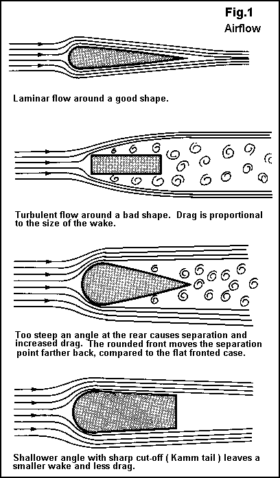
The value of reduced drag was clearly shown back in the fifties when the magazine "Motor Cycle" commissioned a semi-enclosing streamlined body shell to be built around a five year old 350 cc. Royal Enfield. This resulted in a 45 lb. increase in all up weight. But, such was the value of lower drag that even acceleration in the 15-40 mph. range was significantly improved, as the table of performance shows. These tests were carried out by Vic Willoughby at MIRA. using electronic timing gear. Trying to reconcile these results into a percentage reduction in drag has its problems, largely because all tests were done with unchanged gearing. Thus, the engine revs. and hence the BHP. produced would probably have been different during the maximum speed runs, depending on whether the bodywork was fitted or not. However, by making one or two assumptions, I have calculated that the drag with the body was probably in the range of 75/85% of the unfaired machine. So, if this order of performance improvement is possible with such a body, just imagine what could be achieved with a purpose built device,---- a well streamlined FF. for example, with a smaller frontal area as well as the possibility of a better shape. O.K. so what shape is best from the drag view point? Well, the classic tear drop shape would be hard to beat, and an approximation to this was used very successfully by NSU. to take many world speed records in the smaller classes, back in the fifties. However, the length to width ratios needed for minimum drag would render a normal motorcycle too long. To shorten the body by bringing the rear in at a steeper angle would only cause turbulence and increased drag, it is much better to design a long thin body and just cut it off at the tail to give the required length, this sort of fools the air into almost acting as if the tail portion was still there. This is known as a Kamm tail after the man who first thought of it. Even with a Kamm tail a conventional bike is difficult to streamline really efficiently because of the various cutouts needed for practical reasons, such as getting on it and putting one's feet down when stopped etc. Improvements can certainly be made though, against most current emphasis the place to start is at the rear of the machine, the flow around the high pressure areas at the front can reasonably well take care of themselves, but anything that smoothes the flow at the back and helps reduce the size of the wake would really be beneficial. In fact many pointed front shapes would produce less drag if turned around, as shown in fig. 1 anything can be done to alleviate them.
LIFT.
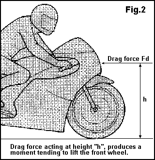
Aerodynamic lift, particularly over the front wheel is potentially dangerous, because it reduces the hold of the tyre/s on the road. It is not always realised that, even with a body shape that produces no nett lifting force there is still a tendency for weight transfer off the front wheel and onto the rear due entirely to the effect of the drag force. Consider fig.2 , the drag force, Fd, can be considered to act through a single point, at a finite distance above the ground, h. This produces a torque trying to rotate the bike about its rear wheel, thus lifting the front.
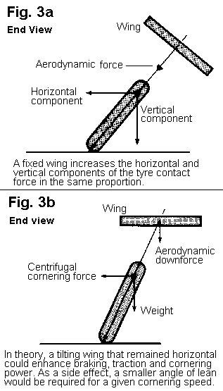
So, all else being equal, anything that reduces drag and/or the effective height at which it acts, will help reduce this weight transfer. In addition to just reducing drag the ideal situation would be for the body shape to create a down force at the front and a lifting force at the rear to exactly balance the above effect. Led by BMW. with their R100 RS. fairing this problem is now receiving more attention from the manufacturers. It is sometimes suggested that as racing cars, nowadays, benefit so much from the tremendous aerodynamic down thrust that their bodies generate, that the same advantages in cornering power could be used on bikes. Here again, as in so many aspects, our need to lean a bike for cornering complicates the issue. In a straight line, any aerodynamic features that create extra down force will load the tyres more and make available more traction. Provided that our brakes are good enough and that we have sufficient power, this greater grip will allow for better acceleration and braking. It is when we come to cornering that the situation is different. Assume that we get our extra down force by use of a wing as in fig.3 , then as we lean into a corner this force acts in line with the bike and hence increases the horizontal force in direct proportion to the increase in the vertical force on the tyres. Therefore, any increase in the tyre's ability to support greater corning forces is used up by the horizontal component of the aerodynamic force. In practice cornering speed may well be actually reduced, because the coefficient of friction of the tyres with likely be reduced with the extra load. A racing car benefits because it does not lean to any significant extent and the force acts down vertically, so to do the same on a bike means having a tilt-able wing that remained near horizontal as the bike leans, or by preventing the bike from leaning ---- perhaps by extreme use of the dragging knee and bum off the seat riding style.
BASIC DIRECTIONAL STABILITY
One of the primary requirements for this is that the sideways Centre of Pressure should be behind the Centre of Gravity. The C of P. is a point through which we can consider the total wind force on the side area of the bike to act. It is this same stability criteria that requires aircraft to have vertical fins at the rear, and darts and arrows to have feathers. The idea works like this:----- When exposed to side wind, if the C of P. is rearward, the back of the machine is blown away from the wind, thus causing the front to point into the wind and automatically correct for the tendency to be blown off course. On the other hand, when the C of P. is towards the front then this end gets blown with the wind and the bike will steer with the breeze away from its original course, a basically unstable condition and only the intervention of the rider can keep things under control. Achieving a rearward C of P. is harder than talking about it, Conventional motorcycles tend to have most if not all of their bodywork in front of the rider, a legacy from the short-sighted FIM. decision in 1957. to severely restrict the design of racing streamlining, and so a forward C of P. is inevitable with a normal layout. Ironically, even with a purpose designed streamlined body with plenty of side area to the rear it is often even more difficult to achieve the desired end. To understand why we need to look a little closer at the detail of the airflow around such a machine.
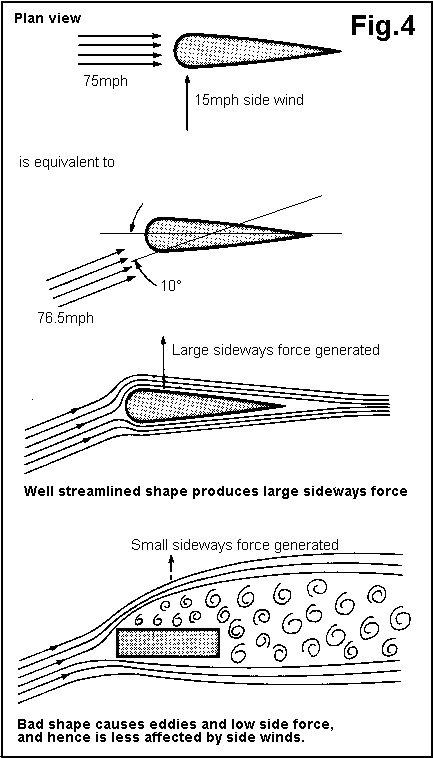
Fig.4 , shows how, at speed, a side wind does not really act as a side wind at all but combines with the effective head wind, from the bikes motion, to create an airflow at an angle to the machine. e.g. If the bike is travelling at 75 mph. with a side wind of 15 mph. then the effective breeze will be at 76.5 mph. acting at an angle of about 10°. A well streamlined section, such as an aircraft wing will produce very high forces at such an angle of incidence, on an aircraft these forces act as lift, and their magnitude is amply demonstrated every time a 747 takes to the air. On a road vehicle these forces act as side forces on the machine, and we wish to reduce their magnitude so that the disturbing effect is minimised. A badly streamlined shape would make a very poor aircraft wing because the degree of lift would be low and the same consideration applies on the road, the magnitude of the sideways disturbing forces will generally be reduced with a high drag design. A real motorcycle fits somewhere between the ideal ( for drag reasons ) teardrop shape and a brick with wheels. The air flow around the front area of the machine will be reasonably ordered but at some point along its length separation will occur and the flow rearward of this point will be turbulent. When this occurs the side area exposed to this disturbed flow will not be effective in keeping the C of P. towards the back. As speed gets higher, the separation point tends to move frontward and so does the C of P., so instead of aerodynamic stability improving as we go faster the usual tendency is unfortunately just the opposite. Streamlined record breakers often have huge tail fins in an effort to redress the balance. Talking of balance, this is also disturbed by sidewinds, as the rear view in fig. 5 shows.
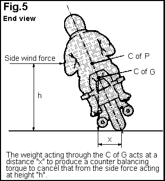
The side force produces a torque tending to make the bike fall over away from the wind, to retain balance it is therefore necessary to lean the bike into the wind. Under these conditions, the weight of the machine now acts away from the centreline of the bike and produces a torque which balances that from the wind force. To reduce the degree of lean necessary, we need to generate a small side force combined with a low C of P., to give the minimum disturbing effect, and a heavy bike with a high C of G. to minimise the reaction from the bike to this disturbance.
DYNAMIC DIRECTIONAL STABILITY.
The above refers to the steady state conditions of a constant side wind. In practice, this is rare and gusty conditions are more usual. Apart from varying wind, gaps in hedgerows and the wakes and bow waves of lorries on motorways all contribute to our problems. The full dynamic effects of all this on a bike is extremely complex but we can look at some of the main features. As I have pointed out in previous articles, roll or leaning motions of a bike are intertwined with yaw or steering motions. This can lead to destabilising effects under gusty conditions. Consider a sudden blast of air from the left hand side, the bike will respond by a sudden roll movement away from the wind to the right, this in turn, through precessional effects, will cause the steering to turn to the right, and hence the bike will tend to steer away from the wind rather than into it as we would like. But this turning tendency to the right will, through centrifugal force, try and make the machine lean to the left which is what we need to maintain balance. ----- See what I mean by saying that this whole business is very complicated! In 1986 I converted a Gold Wing from telescopic forks to one of my "hub centre" front ends, for its owner, Wayne Boys. After he had had it for a while we discussed the various effects that he noticed in normal riding, many observations were as I had expected but I was a bit surprised when he pointed out that it was far more stable in gusty side winds. At first I thought that this was probably just due to the greater lateral stiffness of the new suspension, which is generally more stable anyway. But a bit more thought as to the differences between the two setups, shed a bit of light on why they should behave so differently under these conditions. There seemed to be three main differences, in addition to the stiffness already mentioned ;----- 1. 16" wheel instead of 19", 2. Less trail, 3. A 17 rake angle which needed zero offset between the steering axis and the wheel centre-line to achieve the desired trail. It can be argued that all three of these changes work toward improving the performance in gusts. Smaller wheel;----- The precessional forces will be reduced in line with the reduction in weight close to the wheel/tyre circumference. This will reduce the coupling between yaw and roll movements.Less trail;----- The component of the wind side force, acting at the front of the machine is passed to the road surface through the tyre via the steering axis, but the steering axis is in front of the tyre contact patch by the amount of the trail, and hence the sideways force on the bike will tend to steer the wheel with the wind. Exactly the situation that we might wish to avoid.Zero offset;----- With normal steering geometry with about 1-2" of offset, the bulk of the wheel side area is forward of the steering axis, this combined with the effect of today's large tyres and discs means that a considerable steering force can be generated by the action of a side wind on the wheel. But with the zero offset geometry used on the hub-centre arrangement, this wind force is balanced about the steering axis and no turning effect is produced. An interesting feature that I noticed when riding my QL. to last year's Milan show, was the effect that tyre pressures had. The QL. has a streamlined body with a fairly large side area, and so the magnitude of the side wind forces may be expected to be high. Now, while the machine appeared to be aerodynamically directionally stable, it would squirm about alarming if the tyre pressures were allowed to drop. This happened due to what was later discovered to be a slow leak at the valve on the front wheel. It appears that the reduced lateral stiffness of the tyres when under inflated, allowed the machine to move about excessively under the action of the high lateral wind force. Photo of the "Flying Hammock"
CONCLUSIONS
Aerodynamic design of motorcycles is more than just a matter of producing a low drag, low lift body with a C of P. behind the C of G. Stability is harder to achieve with well streamlined low drag bodies, this is due both to the greater side area present with such fairings and to more efficient production of "sideways lift" due to the angle between the airflow direction and the direction of travel. So ideally we want a combination of sometimes conflicting requirements:------ Minimal drag for performance and fuel economy. Low frontal C of P. to reduce drag induced weight transfer. Low and rearward side C of P. to reduce the unbalancing moments, and give directional stability. A shape and value of side area that minimises the side force produced. A high and forward C of G. combined with a large weight to minimise the effect of whatever side forces are generated. If any of you out there were thinking of designing your own bodywork, don't let this put you off. Often the amateur with limited resources shows up the large companies, who do not always get it right, even with their wind tunnels. Just look at Ford's attempt with the Sierra, initially there were stability problems until they fitted spoilers to the rear quarter lights. In the bike world, back in 1981 a road test on BMW's Futuro fully faired concept bike, showed it to be very bad in this area too.
